
Quantum circuits are composed of quantum gates and are used to perform quantum algorithms. A quantum circuit is a series of quantum gates that act on one or more qubits. The gates are arranged in a specific order, and the circuit is executed in a specific sequence
A Quantum Circuit is a model for quantum computation that describes how qubits are initialized, manipulated, and measured through a sequence of quantum gates.
It serves the same role in quantum computing as logic circuits do in classical computing — but instead of using irreversible logical operations (AND, OR, NOT), quantum circuits use reversible unitary operations that exploit superposition and entanglement.
In simple terms:
A quantum circuit is a series of quantum gates acting on qubits to perform a computation, followed by measurement to produce a classical result.
1. Structure of a Quantum Circuit
A quantum circuit consists of three main stages:
- Initialization — Qubits are prepared in a known starting state (usually |0⟩).
- Manipulation (Processing) — Quantum gates act on qubits to create superpositions and entanglement.
- Measurement — The qubits are measured, collapsing them into classical bits as output.
Representation
Quantum circuits are represented diagrammatically:
- Horizontal lines represent qubits.
- Boxes or symbols on the lines represent quantum gates.
- Time flows from left to right.
- Vertical connections indicate multi-qubit interactions (e.g., CNOT).
2. Mathematical Description
Mathematically, a quantum circuit implements a unitary transformation UUU on the combined state of all qubits in a quantum register.
If a system has n qubits, its state is represented by a 2ⁿ-dimensional complex vector ∣ψ⟩|\psi⟩∣ψ⟩.
A circuit applies a sequence of gates: ∣ψout⟩=UkUk−1…U1∣ψin⟩
Each Ui corresponds to a gate, and the entire circuit corresponds to their product (composition).
Since each gate is unitary, the overall operation is also unitary — ensuring reversibility and probability conservation
3. Components of a Quantum Circuit
3.1 Qubits
The fundamental data carriers — can exist in a superposition of |0⟩ and |1⟩: ∣ψ⟩=α∣0⟩+β∣1⟩
3.2 Quantum Gates
Operators that modify the qubits’ state vectors.
They can act on one or multiple qubits and are represented as matrices.
3.3 Entanglement Links
Multi-qubit gates (like CNOT) create entanglement, correlating qubits within the register.
3.4 Measurement
At the end of the circuit, qubits are measured, collapsing superpositions to classical results (0 or 1).
Measurements are represented by meter symbols (⟨M⟩) in circuit diagrams.
4. Example: Simple Quantum Circuit
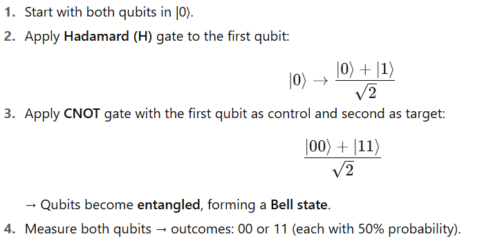
Let’s look at a 2-qubit circuit that generates an entangled Bell state:
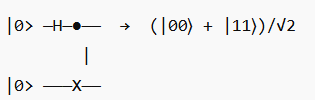
Explanation
Quantum Circuit Diagram Notation
| Symbol | Gate Name | Function |
|---|---|---|
| H | Hadamard | Creates superposition |
| X, Y, Z | Pauli Gates | Rotations / bit-flip / phase-flip |
| S, T | Phase Gates | Phase rotations |
| ⊕ (circle with +) | Target of CNOT | Flips target if control is 1 |
| ● (filled dot) | Control qubit | Triggers controlled operation |
| ⊗ | Measurement | Converts quantum to classical state |
These symbols combine to describe any quantum algorithm graphically.
6. Multi-Qubit Quantum Circuits
Quantum circuits can include multiple qubits, allowing entanglement and parallelism.
For example, a 3-qubit circuit might perform controlled operations, quantum addition, or Grover search iterations.
Each additional qubit doubles the size of the state space —
→ an n-qubit circuit operates on a 2ⁿ-dimensional vector space.
7. Measurement and Output Probabilities
When measurement is performed:
- Each qubit collapses to 0 or 1.
- The outcome follows a probability distribution given by the squared magnitude of amplitudes in the quantum state.
For example, if:
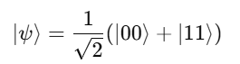
Then:
- P(00)=½
- P(11)=½
This probabilistic output is central to quantum computation — results are often derived statistically through repeated circuit runs.
8. Building Quantum Algorithms Using Circuits
Quantum circuits are composed hierarchically — smaller subcircuits form the building blocks of larger algorithms.
Examples:
- Quantum Fourier Transform (QFT): Chain of Hadamard and controlled phase gates.
- Grover’s Algorithm: Sequence of oracle and diffusion circuits.
- Shor’s Algorithm: Combines modular exponentiation and QFT circuits for factorization.
Each algorithm can be represented as a circuit diagram that maps qubit interactions and transformations step-by-step.
9. Simulation and Programming Tools
Modern quantum programming frameworks allow users to design and simulate circuits before executing them on real quantum hardware.
| Framework | Developer | Feature |
|---|---|---|
| Qiskit | IBM | Circuit-based design, access to IBM Q hardware |
| Cirq | Low-level circuit manipulation | |
| PennyLane | Xanadu | Quantum machine learning and hybrid circuits |
| Braket SDK | AWS | Cloud access to multiple quantum devices |
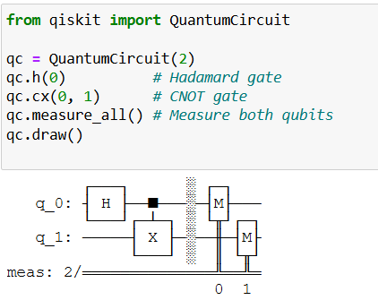
Example (Qiskit):
10. Circuit Depth and Complexity
Two key metrics determine circuit performance
| Metric | Meaning |
|---|---|
| Circuit Width | Number of qubits used |
| Circuit Depth | Number of sequential gate layers |
- Shallow circuits (small depth) are desirable since qubits decohere quickly.
- Optimized compilers aim to minimize depth and reduce gate errors.
In quantum hardware, longer circuits mean higher error accumulation, so efficient design is critical.
11. Visualization: Bloch Sphere and Circuit Evolution
A quantum circuit’s gates correspond to rotations on each qubit’s Bloch sphere.
When multiple qubits interact, their combined state moves through a multi-dimensional Hilbert space — beyond visualization, but mathematically tractable.
12. Noise and Real Hardware Considerations
In real devices:
- Each gate introduces small errors.
- Crosstalk between qubits can distort operations.
- Decoherence limits how deep a circuit can go before the state collapses.
Quantum circuit design must therefore balance algorithmic power with hardware constraints, often using error mitigation and noise-aware compilation.
Summary
| Concept | Description |
|---|---|
| Definition | Sequence of quantum gates operating on qubits |
| Operation Type | Reversible unitary transformations |
| Representation | Circuit diagrams (gates on horizontal lines) |
| Purpose | Implement quantum algorithms |
| Core Components | Initialization, gates, entanglement, measurement |
| Output | Probabilistic measurement outcomes |
| Optimization Goal | Minimize depth, maximize fidelity |
| Tools | Qiskit, Cirq, PennyLane, Braket SDK |
14. Conclusion
Quantum circuits form the computational core of quantum computing.
They provide a visual and mathematical framework for describing how qubits evolve from an initial state to a measurable result through sequences of unitary transformations.
Through quantum circuits, we can design and execute algorithms that exploit superposition and entanglement, enabling exponential speedups in areas like cryptography, optimization, and machine learning.
In essence:
Quantum circuits are the language of quantum computation — each gate is a word, and together they form algorithms that harness the full power of quantum mechanics.